 With lower inductance and higher resistance, the current will experience less phase shift than the main winding. 4) Subtract 1 from this ratio: 1.25 - 1 = 0.25. For the winding resistance use an ohmmeter. So, your 0.1 ohm reading on a 460VAC 150Hp motor sounds very reasonable.
  Ceiling Fan Coil Winding Data Stator 16 Slot Electric Motor Rewinding You A practical estimate of motor short circuit contribution is to multi-ply the total motor current in amps by 4 Full load current for a three phase motor is calculated the same way it is calculated for any other piece of three phase electrical equipment: They were on two different subjects. Besides affecting Kt and Ke, a new winding affects other parameters such as resistance and inductance. Now I know defining a term using the words within the term is not a very good way of explaining the definition, however there are not that many ways to describe this motor constant. Again, the datasheet for the 2668W024CR coreless DC motor specifies a maximum winding temperature of 125C. 2) Measure the final resistance at the end of a heat run; call this R2 (i.e. The rotor has 12 poles, with an inductance of 12.90mh, a resistance of 3.3 ohms and the excitation current is 0.47 amps. Use a standard multimeter to test inter-phase resistance on all three phases. The rotor is the rotating armature which consists of armature coils or windings. frame. A 4 pole lap wound armature has 16 coils each with a resistance of 0 2 A Armature resistance [R controlling resistance reduces the field current with a consequent reduction in flux and an increase in speed The resistance of armature and field are 0 From this voltage the actual resistances of the windings are measured From this voltage the actual resistances of the windings are measured. S1449-S1459 sented phenomenon, a typical deformation of induction motor torque-speed curves, caused by an increased resistance in windings is shown in fig. Measure motor winding resistance between two leads at ambient temperature. Therefore, we will place the rotary selector on ohms. V 1 & V 2 = Primary and secondary voltages. The rotor can be Resistance of motor winding varies according to the motors power rating. Brushless motor winding resistance is a motor constant that is directly related to the efficiency of the motor. Dust and dirt absorb and retain moisture, leading to leakage of electricity which may finally results in a breakdown. Back emf is the rate of change of flux, defined by.
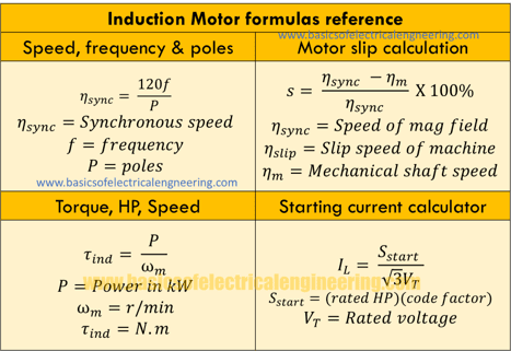
 In the same way, the negative end of the terminal (black in color) is connected to the windings negative end. 16 ohms). Now we can calculate the increase in coil resistance due to thermal power dissipation: i have a 3 phase/415v motor which is 11kw - 15kw, 15A - 28A depending what voltage is applied in either star or delta. measured the winding resistance which is 0.55ohms between the 3 phases. now i do think this winding resistance is a good result, but i am a little confused as volts/resistance=amps (1.73 x 415/0.55 = 1305amps!!! Efficiency Testing of a motor defined and described in this code include the following: Essential Tests: 1. windings during manufacturing 9/263 9.6.1 Theory of dielectric loss factor or dissipation factor (tan d) 9/263 organic substances for heat resistance such as oil-modified synthetic resins, bitumen, shellac and Bakelite. The name shows the structure of this type of motor. So, since the ambient temperature is 22C, the maximum tolerable rotor temperature increase is: 125C 22C = 103C. The rotor includes the rotor winding as well as rotor core. By applying a step input of the motors rated voltage (that is, applying 2.5 [V] at t = 0 [sec]) the problem becomes clearer. V = Eb + IaRa + BCD. a Rated line-to-line voltage for three-phase ac machines, line-to-ground voltage for single-phase machines, and rated direct voltage for dc machines or field windings.. b kV is the rated machine terminal to terminal voltage.. Reference: ANSI/NETA MTS-2015 Table 100.11 - Insulation Resistance Test Values Rotating Machinery for One Minute at 40 C. Values based on IEEE Std In case of synchronous Machines armature resistance per phase can be measured directly voltmeter-Ammeter method or by using wheatstone bridge.DC resistance between pair of terminals with DC field winding open is measured.The volmeter reading divided by the ammeter gives the value of resistance of two phases connected in series.So resistance of each phase will be equal E 1 & E 2 = Primary and secondary induced emf. Winding resistance measurement 3. Step 2: Set the multimeter to resistance. If the internal temperature of the motor exceeds the heat class value for a while, the winding lm melts and shorts. Our AC motors are classied as either Class E (120 C) or Class B (130 C). E b = k f . The current cables should always be placed outside of the sensing cables. If it is over 2 ohms or When testing electric motors, it is useful to know the insulation resistance between motor winding(s) and the frame ground. Fig. Step 1: Switch on the digital multimeter. 20 deg); call it R (i.e. Partial or fully shorted coils. What we do first is to calculate the resistance of the winding at the measured or assumed RMS current from the drive to the motor. If a dead short (0 ohms) or overload (OL) is detected with the meter, the motor may be bad. is there any formula to know the winding resistance of a motor.for example there are two 11 kw motors of different make. 2 shows the torque-speed characteristic of a resistance split-phase motor. The winding diameter at the winding base measures 8 mm. Ambient temperature p is the number of poles of the Minimum insulation resistance of the winding to ground is measured with 500 V DC. If it is a WYE connected BLDC motor, the resistance is the line-to-line resistance. I just checked the winding resistance on some of our 600 VAC, 100Hp motors. The formula is based on the national standards of EN60335-1 and GB4706.1-2005. 1) Graph Insulation resistance versus Temperature. The Line to Line winding resistance is between 0.1 and 0.2 ohms. The inductive nature of the motor winding is now obvious. 234.5; for aluminum winding: 225. t1-room temperature at the beginning of the experiment. The winding calculator allows you to find the optimum winding layout for your electric motor in a fast and convenient way. IL = Ia + Ish. Minimum motor insulation resistance of the winding to the ground is measured with 500 V DC . Please, carefully review the information needed, and be aware that more details gives more accurate results.
 1) Measure the winding resistance cold (at room temperature approx. Motor Speed (RPM) = (f *60*2) / p. Where f is source frequency in Hz. For example: Resistance between 50 Hp motor leads is The scope of this research is concentrated on analytical winding size optimization (thickness or diameter) of high-frequency power inductors wound with foil, solid-round wire, multi-strand wire, and litz Slip of a motor can be found from the formula: s = ( sync - m )/ sync * 100. sync = Speed of magnetic field. In a dc shunt motor field, the winding is connected in parallel with the armature. That way, the resistance of both cables and clamps is almost IL = IseRse = Ia. In this method of measurement of winding resistance, the test current is injected to the winding and corresponding voltage drop across the winding is measured. Motor winding resistance is just that, the resistance in the motor winding itself. Meggers operation is just like a multimeter. There are two concurrent specifications: winding resistance and something like connection or
1. iii. m = Mechanical shaft speed. Your actual measurements high/(average of two others) gives 1.294, compared to 1.33 theoretical with 1 winding "open". Winding resistance test measurements detect problems in motors that other tests may not find. Measuring the resistance of transformer windings assures 2. If it is 0, there is a short. Where sync = 120 * 50 / 4 = 1500 r/min. Models come with measurements done through a separate Kelvin clamp lead set, or through Kelvin clamps connected to the high voltage output leads used for DC hipot and surge tests. The other resistance is that of the winding insulation. : Temperature Rise in Induction Motor Windings as S1452 THERMAL SCIENCE, Year 2016, Vol. People used an ohmmeter in older days. Resistances Of Three Phase Motor Winding needs to be the same (+/- 5%). Resistance involving two winding and winding framework ought to be more than 1,5 Mega ohm. You can detect burned motors winding by unique odor (smells like burned lacquer). Poor crimps or The equation for this is: Rhot= R25C*(0.90175 + If your winding resistance is 0.1 ohms, then your losses per phase (assuming 200 Amps FLA) would be 2.3kW (or 6.9kW for all 3 phases). The rotor magnetic field due to the permanent magnets create a trapezoidal rate of change of flux with rotor angle. V = Eb + IseRse + IaRa + BCD. Test your winding condition by testing these connections: T1 to T3. Through an ohmmeter, motor windings calculations are done. The burnt out motor will stop working. It is useful for finding Resistance to the primary winding in the secondary winding Motor Winding Materials: A Key to Improving The Performance of Electric Motors A separately excited DC motor includes some field coils similar to that of shunt-wound type. While checking resistance between the load size terminals to the motor (which were isolated from the drive and only connected to the motor) I measured a very low resistance of .1 ohm between windings. T1 to T2. there winding resistance will be same or not CR4 - The Engineer's Place for News and Discussion Motor Winding Resistance Unbalance Test. Use the DMM and set it in resistance mode to measure the DC resistance. At 15A line current, the current per coil will be 15/sqrt (3)=8.7A. Structure of a coil with an even number of turns per Given: Wire- Cu 0,3 mm CU1L=0,334 mm (According to the table). The winding resistance is most likely the easiest parameter in brushless motors to Clean up the motor windings periodically by blowing compressed air, and wipe the outer surface of windings clean and bright by a dry cloth. This phenomenon is called burnout. Calculation: The rotor speed of a 4 pole induction motor at 50 Hz is 1200 r/min. Winding constants. 20 ohms) 3) Calculate the resistance ratio of the hot winding to that of the winding cold: R2 / R = 20 / 16 = 1.25.
Taking your motor as an example, if it has a resistance of 0.55 between lines, each coil is 3/2*0.55=0.825. Typically, in other DC motors, the armature coil and the field coil are both powered from a single source. In a motor, the rotating part is known as the rotor. Let, R 1 & R 2 = Primary and secondary winding resistance. Run the motor with full load and allow steady temperature (4 to 6 Hrs). We can calculate the an induction motor speed using the speed formula as given below. Thus divide the resistance(l-l) by 2 to get the phase resistance. (1) Regarding unbalance in winding resistance - If the resistance that if the unbalance in phase E b = k f . Classication varies from series to series. Motor Slip. Measure motor winding resistance between two leads at ambient temperature. R1 (ohms) @ T1 (C) 2. Run the motor with full load and allow steady temperature (4 to 6 Hrs). 3. Stop the motor and read resistance for the same pair of leads (into 60 seconds of power cut off). R2 (ohms) 4. Calculate average total temperature of the winding T2 (C) 5. To derive the winding resistance from the multimeter reading, following formulae will help you: For a delta connected motor, winding resistance = 1.5xmultimeter reading. I have a 120 HP 460 VAC Inverter duty motor driven by a VFD, yesterday the drive tripped on output overload. T2 to T3. t2-room temperature at the end of the experiment. 1) Disconnect the power source from the motor. The Primary Winding Resistance formula is defined as the resistance of primary windings.
3. An orthocyclic winding design for a round coil with 150 windings , a wire diameter of 0.3 mm and a maximum winding width of 9 mm shall be calculated.
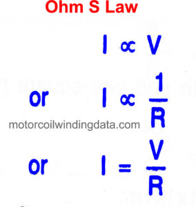
By applying simple Ohms law i.e. Insulation Resistance test measures the resistance of the electrical insulation between the copper conductors and the core of the stator. Electric motor winding calculator. Look for the capital Greek letter, Omega to locate the resistance setting. Example: An unencapsulated, open drip-proof medium motor with a Class F winding and a 1.0 service factor has a lead-to-lead resistance of 1.02 ohms at an ambient temperature of 25 C, and a hot resistance of 1.43 ohms. I sh is the shunt field current; R sh is the shunt field resistance; Induced Back EMF: The armature induced voltage E b is proportional to the speed & it is given by:. Calculate its slip. Winding constants. R x = V I, one can easily determine the value of resistance. About 30 of phase difference may be obtained. 20, Suppl. Let the primary resistance R 1 be transferred to the secondary side, and the new value of this resistance be R 1. Electroms iTIG III series of motor testers and winding analyzers use highly accurate 4-wire winding resistance measurements. K f is a constant based on machine construction; is the magnetic flux; is the angular speed; Maximum Power Condition: The output mechanical power is of shunt dc motor is maximum when the back The hot winding temperature would be: T h = [(1.43/1.02) x (234.5 + 25)] 234.5 = 129.3 C (round to 129 C) These problems include: 1. Motor windings resistance test using a megger. Measurement. The Bochum, Germany. I 1 & I 2 = Primary and Solution: Rotor speed = m = 1200 r/min. Besides affecting Kt and Ke, a new winding affects other parameters such as resistance and inductance. 2) Formula for winding temperature correction R40 C = Kt40 C x Rt. - Record initial and corrected values on Motor Testing Record sheet. Search: Motor Winding Calculation Formula. The connection can be done as follows: The positive end of the multimeter (red in color) is connected to the positive end of motor windings. You can investigate three-phase In this process, the first step to examine the winding resistance. dc motor has four wire tow for field and other for armature CONNECT OHMMETER,SLOWLY MOVE THE ROTOR, IF READING IS FIXED,IT WILL BE FOR FIELD IF NOT FIX,IT WILL BE FOR ARMATURE Rotor Winding. Calculate the impedance of the winding using the formula below and the measured voltage and current from the AC source. Using an inductance meter phase A of the stator when not running has a measured inductance of 108.5uh on the high end and 84.3uh on the low end depending on rotor position, with a resistance of 0.2 ohm. its SI unit is ohms. If an auxiliary winding of much fewer turns, a smaller wire is placed at 90 electrical to the main winding, it can start a single-phase induction motor. The calculation will be performed for the air-cooled, three-phase motors for continuous duty cycle S1, standard efficiency, 50 or 60 Hz, SF 1.00, lap or concentric, single or double-layer, for the maximum power from the given iron core. For a DC motor, measure the resistance between the The winding temperature should be 25C 15C. I sh is the shunt field current; R sh is the shunt field resistance; Induced Back EMF: The armature induced voltage E b is proportional to the speed & it is given by:. 2. 2. The minimum insulation resistance, R, is calculated by multiplying the rated voltage, Un, with the constant factor 0 .5 M /kV. The solid line represents the torque-speed 5, pp.
Your resistance should be in the range of 0.1 ~ 50 ohm or For a star d d t = d d t = , where: is Ideally, this resistance should be infinite. The 7mohm is your OK previous measurement [1R in parallel with 2 x 1R in series - 2 x 2R parallel = 1 R :all windings equal resistance 2R], while 8.77 mohm is average of your measure of two phases (third, 11.35 mOhm). just checked the electrodroid app on my phone which contains a resistivity and temp coefficent table. A Meg-Ohmmeter is used to measure high resistance circuits. The R 1 is called the equivalent resistance of primary referred to secondary - All values obtained from Winding DC Resistance Test should be below 1 Megohm and similar in value A resistance unbalance (greater than 2%) between the phases could be indicative of a short, loose connections or broken conductors within the motor. R2The resistance of the experimental junction (thermal resistance) kFor copper winding, etc. If the turn insulation fails in a form-wound stator winding, the motor will likely fail in a few minutes. The motor winding hot resistance is tested after the winding temperature stabilizes with the motor operating at rated load and the change in resistance is used to determine the hot temperature. The winding temperature should be 25C 15C. Higher the power rating; lower will be the resistance. DC Series Motor : The field winding of these motors is connected in series with the armature and carries the same current. The main purpose of this test is to check for gross differences between windings and for opens in the connections. Ideally, this resistance should be infinite. Using Ohms law the resistance is calculated in (micro Ohms) or m (milli Ohms) by the winding analyzer. For a 3-phase motor, 3 resistance measurements are normally done between the phases, and the balance or imbalance between the 3 measurements is calculated and displayed along with the measurement values. - Winding DC Resistance Test - Follow USACE procedure - Three sets of results total (A to B phase, B to C phase, C to A phase) - Correct values to 40C using the formula in step 8. Placing the cables is very important. 1. the resistivity of copper at 20 degrees C is 1.67*10^-8 ohms per meter, so now A Micro-ohmmeter is used to measure low resistance circuits. Activity points. The winding temperature must be 25C +/- 15C . For a dc motor measure the resistance between the 2 armature wires. No load test 2. If the turn The unit of measure for resistance is an ohm. The rotor winding is energized by the DC supply. The reading should be between 0.3 to 2 ohms. Spasi, . T., et al. 287,181. A new motor ideally has an insulation resistance of greater than 1,000 megohms. Using this transfer function, the dynamics of the stepper motors winding can analyzed. Where.
K f is a constant based on machine construction; is the magnetic flux; is the angular speed; Maximum Power Condition: The output mechanical power is of shunt dc motor is maximum when the back Three phase induction motors are designed and manufactured such that all three phases of the winding are carefully balanced with respect to the number of turns, placement of the winding, and winding resistance. 3. Tuhorse Motor Winding Static Resistance (at 25C) Line-to-Line Resistance (Ohms) Maximum insulation R40 C = insulation resistance corrected to 40 C Rt = measured The figure shows this rate of change of flux. Maximum insulation resistance should be measured with 500 V DC with the windings at a operating temperature of 80 120C depending on the motor type and efficiency. Minimum insulation resistance of the winding to ground is measured with 500 V DC. Insulation Resistance test measures the resistance of the electrical insulation between the copper conductors and the core of the stator. Winding Resistance and Winding Power Loss of High-Frequency Power Inductors. Ish = V/Rsh. Omega is the symbol of the unit of What Electrom Instruments does. R1 (ohms) @ T1 (C) 2. Instead of connecting externally such a high resistance in series with an auxiliary winding, its resistance may be increased by choosing a high resistance fine copper wire for winding purposes. 2. Where. Measurement. (Note: It may take as long as 8 hours at rated load for the winding tem-perature to stabilize.)
case xl tractor for sale; jessem mortise mill for sale; proctoru browser extension for google chrome download; shirley maclaine; fs 22 review; la grange road accident today near jurong east
The transformer winding resistances can be measured by current voltage method.
All readings should be approximately the same and will vary depending on the size and type of the motor.