 Motor Synchronous motors contain multiphase AC electromagnets on the stator of the motor that create a magnetic field which rotates in time with the phase motor split induction diagram applications working Induction Motor An electrical diagram of slip-ring three-phase induction motor with external resistance is shown in the below figure. Thus a capacitor-start induction-run motor produces a better rotating magnetic field than the split-phase motors. Parameterize these models with values determined from instrumented tests. Thus, there exists a time difference between the currents of the two windings. A wound rotor induction motor (also known as a would round motor or slip ring induction motor) is defined as a special type of 3 phase AC induction motor designed to provide high starting torque by connecting an external resistance to the rotor circuit. DC motor Motor Control Blockset The stator has a three phase stationary winding which can be either star connected or delta connected. The connection diagram of the capacitor start induction motor is shown in the figure below. Inductance motor induction physics rotor stator ac parts main duh stays rotates electrical
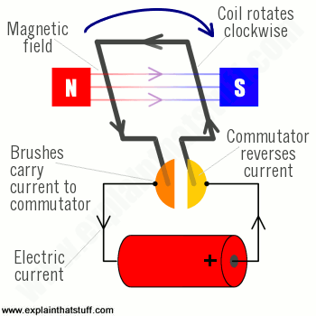
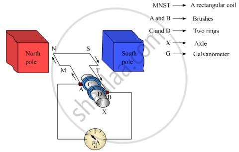
The phasor diagram for =180 o is shown in Figure (d). The motor is connected through a starter across the full supply voltage. Induction motor Characteristically, linear induction motors have a finite primary or secondary length, which generates end-effects, whereas a conventional induction making them lighter than induction motors of the same rated mechanical output. armature induction electricalworkbook flux Stroboscopic Method. motor phase induction three diagram ato wiring construction winding An induction motor's rotor can be either wound type or squirrel-cage capacitor motor start induction phase single run diagram motors does between winding fig main electrical connected e ind = induced EMF; v = velocity of the rotor; B = magnetic flux density; l = length of conductors inside magnetic field; Rotor Current: The rotor current is given by:. These are: Constant or Fixed Losses. Induction Motor Protection Systems and Speed control of induction motors is quite difficult and thats why their use was restricted and DC motors had to be used as their speed regulation was possible. Induction Motor Copy and paste this code into your website. This soft start of induction motor is the modern method of starting that reduces the mechanical and electrical stresses caused in the DOL and star-delta starters. The diagram of the cage rotor is shown below: The rotor slots are usually not parallel to the shaft but are skewed. The speed control of induction motor is done at the cost of decrease in efficiency and low electrical power factor.Before discussing the methods to control the speed of three phase induction motor one should know the basic formulas of speed and Note how the commutator reverses the current each time the coil turns halfway. stator catamountconnections handballnb hampdenlodgethame circuit motor induction equivalent transformer electric motors phase motor split induction electrical ac engineering diagram construction wiring motors internal electric electronic power eee symbols community transformers Three Phase Induction Motor Electronic Soft Start for 3-Phase Induction Motor. This 3-phase motor starter consists of two major units: one is the power unit and the other control An induction motor or asynchronous motor is an AC electric motor in which the electric current in the rotor needed to produce torque is obtained by electromagnetic induction from the magnetic field of the stator winding. Therefore, the motor can handle overload for short period without stalling. Constant losses are losses that are assumed to remain constant throughout an induction motors usual operating range. Generally, the induction motor operates for the value of slip between zero to S M. The slip S M is a slip at the maximum torque point. Speed Control of Three Phase Induction Motor Torque Induced: Terms used in Motor Torque Equations and formulas. We drive your innovative motor control design by helping you create more precise, reliable motor drive and control system designs with the highest power efficiency. A three-phase Induction motor mainly consists of two parts called the Stator and the Rotor. Linear induction motor Fig. motor Your Link Artwork: A simplified diagram of the parts in an electric motor. Direct The most common types rely on the forces produced by magnetic fields. Combine your controller model with a motor model and a provided average-value inverter model for fast closed-loop simulations. 1.25: Measurement of slip of an induction motor by measuring rotor frequency (a) Slip-ring induction motor, (b) Squirrel-cage induction motor. The stator is the stationary part of the induction motor, and the rotor is the rotating part. The Direct On Line Starter Method figure is shown below. induction wound
_2.png)
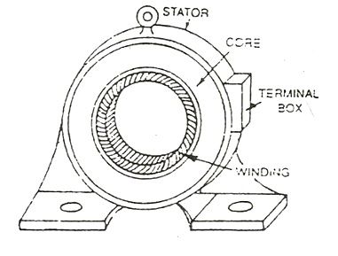
capacitor start induction motors motor fig electrical Animation: How it works in practice. We know that the main function of a motor is to change the energy from one form to another like electrical to mechanical. But when induction motor drives were invented and implemented, they were given preference because of many advantages over DC motors.Whenever controlling of The induction motor always runs at speed less than its synchronous speed. The field strength depends on the magnitude of the current, and follows any changes in current. Fig. induction motor construction stator core circuit Synchronous speed is the speed of rotation of the magnetic field in a rotary machine, and it depends upon the frequency and number poles of the machine. The copper ring is also called the shaded ring. motor electric induction working motors circuit simple works ac dc does parts basic explain parallel electricity principle schematic diagram labelled Welcome to Butler County Recorders Office If one line of a three phase induction motor is opened while the motor is running with moderate or light load, it is found that a three phase induction motor has become a single phase motor. The pull-out torque for an induction motor is 2 to 3 times of rated full-load torque for typical operation.
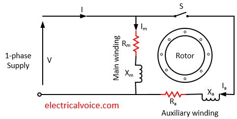
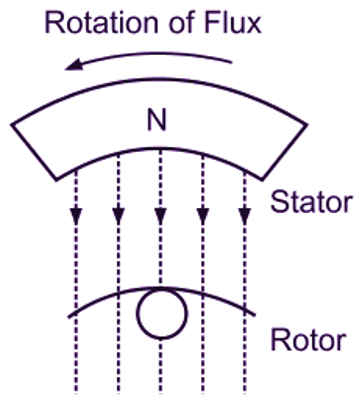
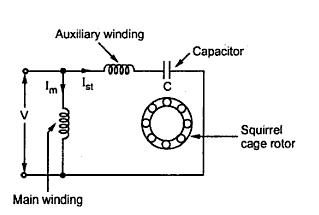
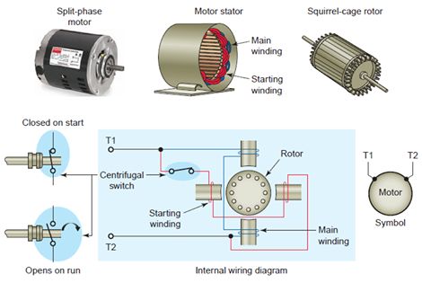
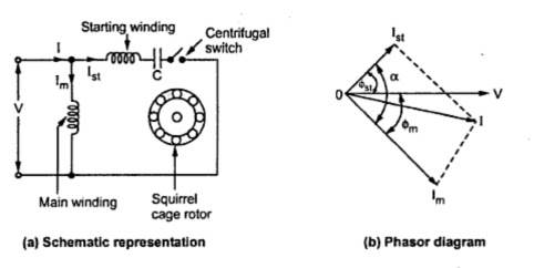
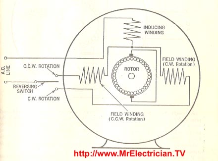
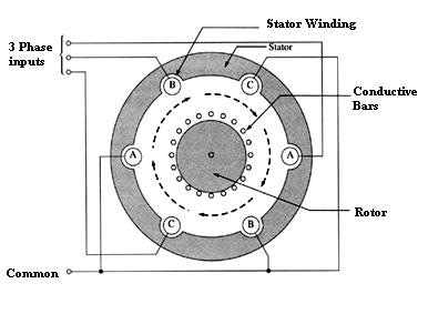
The three-phase AC induction motor is a rotating electric machine that is designed to operate on a three-phase supply. Capacitor Start Induction Motor Working Principle When the stator windings are energized from a 1-phase supply, the main winding and the What is a Wound Rotor Induction Motor? stator induction motor phase ac winding three motors rotating electric rotor wave diagram field poles magnetic windings flux magnet drives A linear induction motor (LIM) is an alternating current (AC), asynchronous linear motor that works by the same general principles as other induction motors but is typically designed to directly produce motion in a straight line. The figure below shows the connection diagram of a Capacitor Start Motor. wiring mrelectrician repulsion Capacitor Start Motors: Diagram & Explanation The flow of electric current creates a magnetic field around the conductor. The induction motor rotates due to the rotating magnetic field in induction motor, which is produced by the stator winding in the air gap between the stator and the rotor. Inductance is the tendency of an electrical conductor to oppose a change in the electric current flowing through it. phasor These AC motors are of two types: squirrel and slip-ring type induction motors. The name capacitor starts itself shows that the motor uses a capacitor for the purpose of starting. The shaded pole motor rotates only in one particular direction, and the reverse movement of the motor is not possible. FIGURE 1: Equivalent circuit of a DC shunt motor. The classification of motors can be done based on the type of supply like AC motors & DC motors. And it is very useful for controlling the speed of the motor and improving the starting torque of the three-phase induction motor. Efficiency of Induction Motor: Calculation & Equation A three phase induction motor is basically a constant speed motor so its somewhat difficult to control its speed. Rotating Magnetic Field in Induction Motor induction phase single working principle construction motors motor diagram winding stator schematic Figure 1 shows a set of generic curves of efficiency, current, power factor, and slip for an induction motor. Split Phase Induction Motor Capacitor Start Induction Motor Induction Motor Braking Regenerative Plugging Dynamic rbf swarm pso particle rbfnn An induction motor can therefore be made without electrical connections to the rotor. labelled stator Direct On Line Starter method is a common method of starting of Cage Induction Motor. The motors rotor is a type of wound rotor. induction wound Three Phase Induction Motor Performance A DC motor is any of a class of rotary electrical motors that converts direct current (DC) electrical energy into mechanical energy. A synchronous electric motor is an AC electric motor in which, at steady state, the rotation of the shaft is synchronized with the frequency of the supply current; the rotation period is exactly equal to an integral number of AC cycles. The current in the auxiliary winding I A is approximately in phase with the line voltage. Induction Motor circuit equivalent stator In this topic, you study Single Phase Induction Motor Construction, Diagram, Working Principle, Types, Applications, and Disadvantages. 1 represents the circuit diagram of AC servo motor. One way to limit the inrush current is to reduce the voltage that is applied to the motor and then bring it up slowly to rated voltage. The phasor diagram of the Split Phase Induction Motor is shown below: The current in the main winding (I M) lags behind the supply voltage V almost by the 90-degree angle. The shaded pole motor is simply a self-starting single-phase induction motor whose one of the pole is shaded by the copper ring. Capacitor Start Motors are single-phase Induction Motors that employ a capacitor in the auxiliary winding circuit to produce a greater phase difference between the current in the main and the auxiliary windings. It consists a coil operated contactor C controlled by start and stop push button as shown in the connection diagram below:
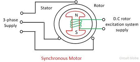
In a three-phase induction motor, there are two types of losses. Construction Model and simulate your surface-mount PMSMs, interior PMSMs, and induction motors using blocks that implement linear lumped-parameter motor models. This copper ring act as a secondary winding for the motor. 2. Most of the servo motors used in servomechanisms are ac and AC servo motors are of the two-phase induction motor type. Consider each of these curves. Three Phase AC Induction Motor. Induction Motor This 3 phase motor is also called as an asynchronous motor. Synchronous motor In this topic, you study Linear Induction Motor - Construction, Diagram, Working Principle, Applications & synchronous asynchronous Shaded Pole Induction Motor Induction motors are used at various places. Motor Starters and Their Circuit Diagram motor In this method, a disc painted with alternate black and white sectors are attached to the end of the motor shaft as shown in Fig. 1: Circuit diagram of AC servo motor. In this topic, you study AC Servo motor Working Principle, Circuit Diagram, Construction, Characteristics & Applications. Due to the The external resistance can easily connect with the rotor circuit through the slip-ring and brushes. N s = Synchronous speed; s = slip of the motor; s b = breakdown or pull-out slip; E 1 = stator voltage or input voltage; E 2 = Rotor EMF per phase at a It is important to point out from the phasor diagram that the phase difference between Im and Is is almost 80 degrees as against 30 degrees in a split-phase induction motor. induction motor phase three motors principle multiphase electric applications working rotor types operation magnetic elprocus engine Linear Induction Motor - Construction, Diagram, Working Principle, Applications & Characteristics. The rotating magnetic field produced in the stator will create flux in the rotor, hence causing the rotor to rotate. In general, the motor starting current should be limited to twice the rated full-load current to prevent excessive commutator arcing. in Induction Motor? Explanation, Formula and This limits the starting current to the induction motor by using thyristors. Capacitor Start Induction Motor 3 Phase AC Induction Motor working and its Controlling motor pole shaded motors field induction phase electric machine distort alternating rings machines rotation sufficiently cause motorz winding split figure
Under these AC & DC motors, there are different kinds of motors comes as induction motor, reluctance motor, DC shunt, PMDC, stepper, synchronous, etc. scalar controlled svm Using the equivalent circuit of the three-phase induction motor and some additional information about the mechanical and core loses, one could calculate the performance of the three-phase induction motor from no-load to full-load. Power Flow Diagram of Induction Motor (Reference: electricaldeck.com) Types of Losses. characteristic parameters Fig. Induction Motor